Development Environments
Software analysis and design
Use case diagrams
Use case diagrams are a subtype of the UML behavioral diagrams. The main purpose of these diagrams is to represent the possible interactions between the user(s) and the system, and also between the different parts of the system itself, and with other systems. This way, we get a general overview of the application, and a graphical representation of the functional requirements, from the point of view of the final user. It is a good guide for the development process that will come later.
Use case diagrams will use actors and use cases to represent the use of the different functionalities or services of the system. We can use many different actors to represent different system roles, so we can see them and their permissions.
1. Elements of a use case diagram
This type of diagram is one of the easiest to represent, since it has just a few different elements, and it is relatively easy to place and connect them.
System
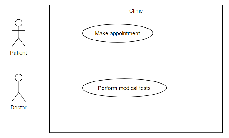
It is the rectangle that defines the system boundaries. Every use case must be placed within this rectangle, and every actor must be placed out of it.
Use case
Use cases represent what an actor wants the system to do. Use cases are a set of actions with a final result. They must always be started by an actor, and they can also launch other use cases. The full set of use cases represents the whole functionality of the system.
Use cases are represented with an oval or ellipse, and they have a name inside, with a verb that indicates the action that will be run (for instance, “Print report”, “Pay the bill”…). In previous example, we can see two use cases, named “Make appointment” and “Perform medical tests”. Use cases can also be named following a given sequence, such as CU1, CU2, CU1.2. Then, later, this sequence is indexed in a table or something similar.
Actor
Actors are users that interact with the system, and start the different actions represented in the use cases.

Actors can also represent the different system roles, or other systems that interact with our system.
Relationships
There are two main types of relationships in a use case diagram. The relationships between actors and use cases are represented by a continuous line, and they mean the beginning of an action started by this actor.
| Relationship | Representation | Meaning |
|---|---|---|
| Communicates |  |
It communicates an actor with a use case. |
For instance, in the example above, the actor Patient can activate a use case called Make appointment.
The relationships between use cases can be of different types, according to the following table.
| Relationship | Representation | Meaning |
|---|---|---|
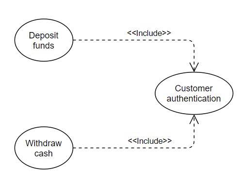
| Include |  |
This relationship is used when a use case includes or activates the behaviour of another use case. |
| Extend |  |
This relationship lets us add new functionalities to existing use cases in certain points called extension points. The arrow points to the base use case from which we want to extend the functionality. |
| Generalization |  |
It is used when a use case or actor is a subtype of another use case or actor. Regarding use cases, is very similar to the extend relationship, so it is only recommended for actors (not for use cases). |
Let’s see some examples of these relationships to reinforce what we have learnt so far.
This is an example of an include relationship. It represents two basic operations in a bank, with two use cases: one called “Deposit funds” and the other one called “Withdraw money”. In both cases, user needs to authenticate in the system, so they both include this use case functionality.
Regarding the extend relationship, we use it to define a use case that is sometimes activated by another use case (but not always, since it would be an include relationship in this case). Then, we draw the arrow from the activated use case to the origin of this activation. Here you can find an example:
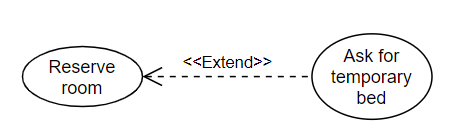
From the Reserve room use case we create an extension point to the use case Ask for temporary bed. If we reserve a room, sometimes (but not always) we may be interested in adding an additional bed to that room. So this is an extension point that is sometimes activated.
Besides, we can also use extend relationship to define use cases that are subtypes of another use case. In the following use case diagram, there are two actors: Employee and Manager They both do their respective work, but, besides, the manager must pay the employee. So we define the “Give Employee Raise” use case that extends the “Do Work” use case to let the manager pay the employee.
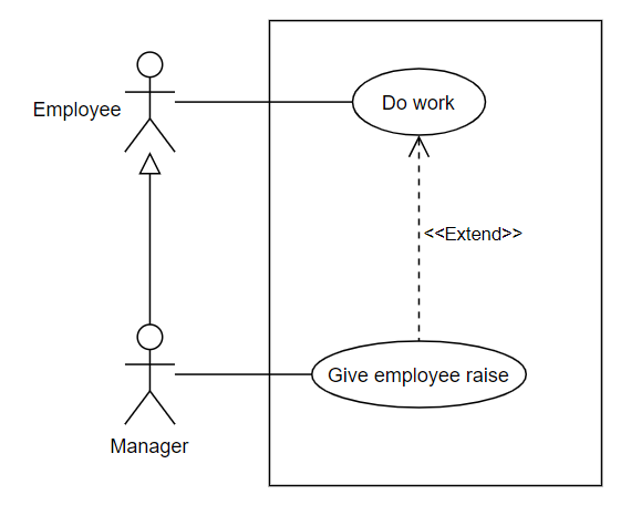
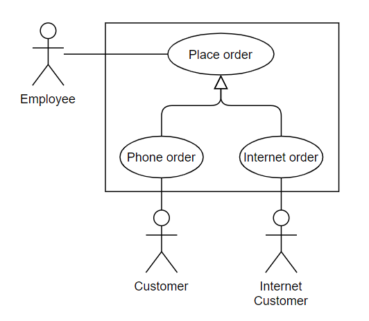
The example above also shows an example of a generalization, since the Manager actor is a subtype of Employee. Below we can see another example of generalization, applied to use cases (although we have seen before that this usage is NOT recommended): we can see a main super-case called Place order with two sub-cases that inherit from it: one for phone orders (Phone order) and the other one for Internet orders (Internet order). Both are different subtypes of the general use case, and they could be reflected as extend relationships as well.
2. A classical example
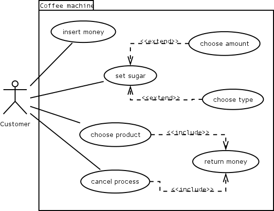
Let’s see how to get a use case diagram from the system requirements. We are in charge of developing a software to control a coffee machine. After talking with the customer, we get the following system requirements specification.
For a user to get coffee from our machine, he must start by introducing enough money. The following step will be to choose the amount of sugar. In our new machine model, users can both choose the amount and type of sugar (white, brown…), and it will be white sugar by default. Once the sugar is set, the user will choose the product (just coffee, coffee with milk, etc.). The machine will return the change once the process has finished and the coffee has been prepared and served. In case the user cancels the operation before choosing the coffee type, the machine will also return his money back.
As we can see, it is a quite detailed specification, but with the use case diagram we can have an overview from the user’s point of view, this is, what the coffee machine is expected to do.
Here you can find some exercises to practice. If you are going to do them using Modelio, we recommend you to place all of them in a single project called Block1, for instance.
Exercise 1:
Design the use case diagram for the following system requirements specification.
A customer asks us to develop a software for a snack vending machine. This machine has a two digit code for each product, and it has five shelves with eight products on each shelf. In the first shelf, products are numbered from 11 to 18, in the second shelf numbers go from 21 to 28 and so on. We must take into account that the machine will not accept the money until the user chooses the product first. The user can cancel the operation at any time before pressing the confirmation button, then his money will be returned. After pressing this button, the machine will move a spiral for the chosen product until it falls to the bottom of the machine, so that it can be taken by the user. Then, the user will be able to take his change back, if necessary.
Exercise 2:
Design a use case diagram for this system requirements specification.
We want to implement an App to solve Sudokus. In order to start a game, the user must choose the “Start Game” option, and then he will choose the difficulty level. Once it is chosen, the game starts. Then, the user will iteratively choose an empty cell, and place a number from 1 to 9, until it completes the Sudoku. During the game, the user can press the “Check” button in order to check if he has solved the Sudoku, or if he has made any mistake. The app will show the message “Everything is OK, you have X cells left”, or “Error in highlighted cells”. In this last case, the cells with wrong numbers will be highlighted. Once the Sudoku is solved, the system will show the message “Well done!”, and the user will see his stats and total time employed.
Exercise 3:
Design a use case diagram adapted to the following system requirements specification.
We want to design an invoice checking module. This module can be accessed either by customers or by business agents, by logging in with their credentials (user and password). When a customer logs in the module, he will be able to search his own invoices, either by date range or by amount. In case a business agent logs in the system, he will be able to search for his customer’s invoices, or by customer and date range, or by customer and amount. Once the search is completed, the module will show in the screen the results.
Exercise 4:
Design a use case diagram for the following specification.
A cultural organization is focused on the loan of two type of objects: music discs and books. We need an application that lets us add new objects to the system from both types. Besides, there are many users that come to this organization. They will need to log in with a user name and password. Then, they may be able to search any disc or book, either by object type (disk/book) and/or by object name (title). Once the object is chosen, they can ask for it if it is not available. Users can have up to 5 objects on loan simultaneously. As this organization is settled in a small town, we don’t expect to have many users asking for books or disks at the same time, so we just need a single computer and a small database to store the information. In case a user does not remember his password, the system will send it by email to the same account that he entered when he registered.